
TAG post originally published on Github by TAG Storage
NOTE: this document is available via this link: https://bit.ly/cncf-cloud-native-DR
Introduction
The purpose of this document is to introduce a new way of thinking about disaster recovery in a cloud native setting.
To do so, we introduce the concept of Cloud Native Disaster Recovery and which characteristics it should have.
To be able to see how Cloud Native Disaster Recovery is possible, we provide the reader with some high-level understanding of the problems that need to be addressed when designing a disaster recovery strategy for stateful applications in a cloud native setting.
In section one, this document covers some definitions around basic availability and consistency concepts and in section two it explains availability and consistency-related concepts that are intrinsic to every distributed stateful workload and that determine the logical design of these applications. In the third section, it provides an overview of the landscape for consensus protocols needed to coordinate different instances of stateful workload clusters. Finally in the fourth and last section it provides some archetypal disaster recovery strategies for container native stateful workloads.
Cloud Native Disaster Recovery – a Definition
We can introduce Cloud Native Disaster Recovery (CNDR) with a compare and contrast table with more traditional disaster recovery approaches (note that for traditional disaster recovery we mean the typical approach used by most companies in pre-cloud era):
| Concern | Traditional DR | Cloud Native DR |
| Type of deployment | active/passive, rarely active/active | Active / active |
| Disaster Detection and Recovery Trigger | Human | Autonomous |
| Disaster Recovery Procedure execution | Mix of manual and automated tasks | Automated |
| Recovery Time Objective (RTO) | From close to zero to hours | Close to zero |
| Recovery Point Objective (RPO) | From zero to hours | Exactly zero for strongly consistent deployments. Theoretically unbounded, practically close to zero for eventual consistent deployments. |
| DR Process Owner | Often the Storage Team | Application Team |
| Capabilities needed for DR | From storage (backup/restore, volume sync) | From networking (east-west communication, global load balancer) |
* The information in this table are generally accepted attributes and measurements for Disaster Recovery architectures
Many traditional organizations have active / passive deployments when it comes to stateful workloads. Sometimes the stateless tier of the application is deployed in an active / active fashion, but the stateful part (database, storage layer) is rarely. In cloud native disaster recovery both stateless and stateful tiers can be deployed in an active / active fashion. In this case by active / active we mean that each and every instance of the stateful workload can take write and read requests.
Notice that active / passive designs are still possible (and common) in cloud deployments, see active / passive examples for more information about that approach.
In traditional disaster recovery, usually there is a human decision involved in acknowledging that a disaster occurred and the Disaster Recovery procedure needs to be initiated. In CNDR, the system needs to autonomously (and quickly) make the decision that a fault has occurred and react to it.
In traditional disaster recovery the actual recovery procedure is often a mix of human action and automated tasks. This is normally due to the complexity of the recovery procedure itself and the fact that it is rarely exercised and, therefore, typically there has not been a focused investment in automating it. In CNDR, the recovery procedure must be fully automated. Combining this with the previous property, the result is that, in CNDR, a disaster event must be treated in a similar way as a HA event.
In traditional DR RTO and RPO (which are the two main metrics to measure a DR procedure effectiveness and will be defined later in the document) can vary from close to zero to several hours. The general narrative is that these metrics can be brought as close to zero as one wants but the cost of doing so grows exponentially as one approaches zero. In CNDR it is generally easier and more cost effective to achieve zero or close to zero. As we will see below, advancements in technology have made this possible without incurring prohibitive costs.
The ownership of the DR procedure formally has always belonged to the app team, which is accountable for business continuity, but often in traditional DR the app team just inherits the DR SLAs of the storage that it uses, de facto yielding the ownership of the DR procedure to the storage team. In CNDR the responsibility is squarely on the application teams who have to choose stateful middleware that is capable of achieving the desired DR SLAs.
Finally, in traditional DR, the main capabilities used to build the disaster recovery strategy often come from the storage team, in the form of ability to do backup and restore or to configure volume replications. As we will see later in this document, the main capabilities needed for building CNDR strategies come from networking, and specifically regards the ability to communicate in a east-west pattern between the geographies of data-center involved in the design and the ability to deploy a global load balancer that can direct traffic to the active locations.
Considerations on Availability and Consistency
A distributed stateful application needs to deal with Availability (the ability to successfully serve requests) and Consistency (the property of keeping state consistent across the various instances that constitute the distributed workload). There is a significant amount of literature around these concepts, here we are going to recap what is important for the sake of our disaster recovery conversation.
Failure domain
Failure domains are areas of an IT system in which the components within that area may fail all at the same time due to a single event.
Examples of failure domains are: CPUs, boards, processes, nodes, racks, entire kubernetes clusters, network zones and data centers.
As one can ascertain from these examples, failure domains exist at different scales.
When deploying a distributed stateful workload, one should consider the various failure domains at hand, and make sure that the various instances of the stateful workload are positioned in different failure domains.
In Kubernetes, there are standard node labels (topology.kubernetes.io/region, topology.kubernetes.io/zone,and kubernetes.io/hostname) to capture the idea of failure domains in a cluster. Designers of stateful workloads should consider creating anti-affinity rules based on those labels when packaging their software to be deployed in Kubernetes.
High Availability
High Availability (HA) is a property of a system that allows it to continue performing normally in the presence of failures. Normally, with HA, it is intended the ability to withstand exactly one failure. If there is a desire to withstand more than one failure, such as two, it can be written as HA-2. Similarly, three failures can be written as HA-3.
The foundational idea of HA is that the Mean Time to Repair (MTTR), a failure must be much shorter than the Mean Time Between Failures (MTBF) (MTTR << MTBF), allowing something or someone to repair the broken component before another components breaks (two broken com
ponents would imply a degraded system for HA-1).
It is often understated that something needs to promptly notify a system administrator that the system has a broken component (by the very same definition of HA one should not be able to determine a degradation solely by the normal outputs of the system).
As a result, a proper monitoring and alerting system must be in place. Otherwise, an HA system would just keep functioning until the second failure occurs (~2xMTBF) and then still be broken, defeating the initial purpose of HA.
Given a failure domain, HA can be thought of as answering the question: What happens to our workload when one of the components of this failure domain breaks?
With regards to stateful workloads, HA implies that one needs multiple instances (at least two) of each workload, and that the state of these instances needs to be replicated between them.
If, for example, one builds a stateful system with two instances and instance A suddenly cannot contact instance B, instance A will have to make a decision whether to keep working or not. Instance A cannot know whether instance B is down or healthy-but-unreachable. It is also possible that instance A is unreachable. This is known as a split brain scenario.
In practice, in a distributed system, failures are indistinguishable from network partitioning where the presumably failed component has become unreachable due to a network failure.
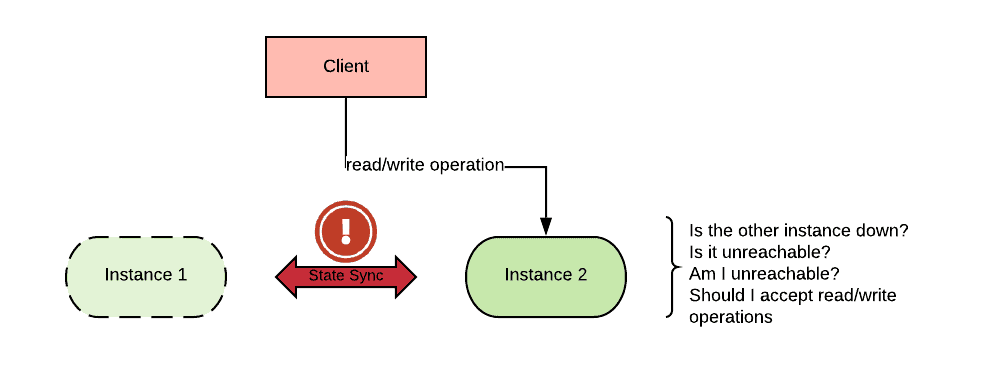
If a piece of software is designed to keep working when the peers are unreachable, its state may become inconsistent. On the other hand, if a piece of software is designed to stop when the peers are unreachable, then it will maintain consistency, but will not be available.
Consistency
Consistency is the property of a distributed stateful workload where all the instances of the workload “observe” the same state.
The realization that by temporarily relaxing consistency, one could build stateful workloads that horizontally scale to a theoretically unlimited size gave birth to a Cambrian explosion of eventually consistent workloads. Typically these workloads expose a NoSQL interface (as the SQL interface is associated with strict consistency), however that is not necessary.
When an issue arises in eventually consistent workloads, two or more sections of the cluster are allowed to have a different state (drift) and to continue serving requests based on the state understood by each member of the cluster. When the issue is resolved, a conflict resolution algorithm ultimately decides which of the available conflicting states wins. This process can take some time, but it is guaranteed to end as long as no other changes occur.
Eventual consistency is not suitable in every scenario (for example financial applications often need to be strictly consistent), and even when it’s applicable, there are several areas of concern including:
- No SLA that can be placed on how long diverged states will take to converge. In situations where the state keeps changing rapidly, the time that it takes to catch up may be lengthy or never resolve.
- Eventual consistency does not mean eventual correctness. While after the conflict resolution phase takes place all instances will be in a consistent state, there is no guarantee that they will end up in the correct state given the logical requirements of the business problem at hand.
The realization of the second point mentioned above has pushed many organizations to seek strictly consistent and available solutions.
The CAP Theorem
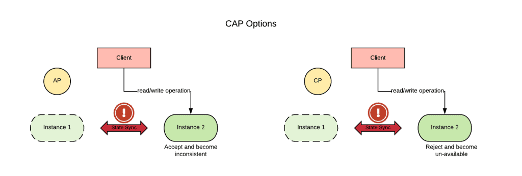
The relation between consistency and availability for distributed stateful workloads is formalized in the CAP theorem. Simply put, the CAP theorem states in case of network partitioning (P), one can choose between consistency (C) or availability (A), but cannot have both.
During a network partition, the stateful workload will need to operate in a degraded state: either read-only if the application chooses consistency, or inconsistent if the application chooses availability.
A corollary of the CAP theorem called PACELC (if Partition, then either Availability or Consistency, Else then either Latency or Consistency) states that under normal conditions (absence of a network partition), one needs to choose between latency (L) or consistency (C). That is to say that under normal circumstances, one can optimize for either speed or consistency of the data, but not for both.
The following table illustrates several stateful workload and their choice in terms of PACELC Theorem:
| Product | CAP Choice (either Availability or Consistency) | PACELC Choice (either Latency or Consistency) |
| DynamoDB | Availability | Latency |
| Cassandra | Availability | Latency |
| MySQL | Consistency | Consistency |
| MongoDB | Consistency | Consistency |
Source wikipedia, see the link for more examples.
The definition of network partition is described with mathematical precision by the CAP theorem and goes beyond the scope of this document, however an approximate but good mental model is the following: if the strict majority of instances can communicate with each other, there is no network partitioning. Otherwise, a network partition has occurred.
So, in terms of HA (i.e. when we account for one failure), if there are three or more instances of a stateful workload, for the CAP theorem we can have both availability and consistency. In general, if the stateful workload is deployed across three or more failure domains, it can be designed to be always available and consistent with respect to the failure of one of those failure domains.
Disaster Recovery
Disaster recovery (DR) refers to the strategy for recovering from the complete loss of a datacenter. The failure domain in this situation is the entire datacenter.
Given a failure domain, DR can be thought of as answering the question: What happens to the workload when all of the components of this failure domain break?
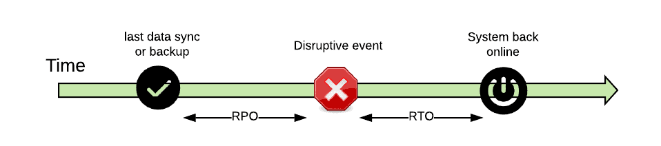
Disaster recovery is usually associated with two metrics:
- Recovery Time Objective (RTO): the time it takes to have systems back online after a datacenter fails.
- Recovery Point Objective (RPO): time interval of state loss from the last saved state to the time the datacenter fails.
In the old days, these metrics were measured in hours, and required that users followed a set of manual steps to recover a system.
Most DR strategies employed an active/passive approach, in which one primary datacenter was handling the load under normal circumstances and a secondary datacenter was activated only if the primary went down.
But, having an entire datacenter sitting idle was recognized as a waste. As a result, more active/active deployments were employed, especially for stateless applications.
With an active/active deployment, one can set the expectations that both RTO and RPO can be reduced to almost zero, by virtue of the fact that if one datacenter fails, traffic can be automatically directed to the other datacenter (through the use of health checks). This configuration is also known as disaster avoidance.
Given the discussion of the CAP theorem, to achieve a disaster avoidance strategy where the stateful workload is always available and consistent, one needs to spread the workload across at least three data centers.
Anatomy of a Stateful application
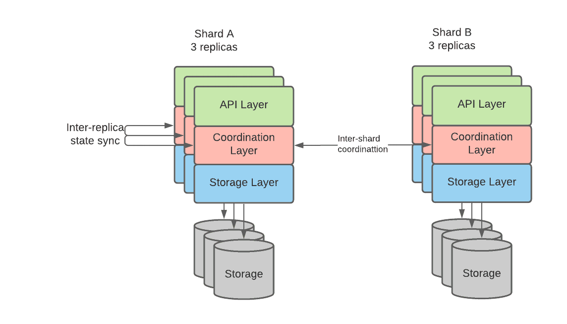
An argument can be made that all distributed stateful workloads share the same logical internal structure because, after all, they are all trying to solve the same complex problem: keeping a shared state consistent while at the same time processing requests in an efficient way.
Granted that actual implementations can greatly vary, the following diagram represents the logical internal structure of a distributed stateful workload:
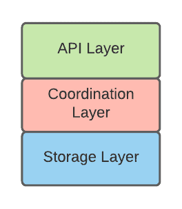
API Layer
The API layer is the component that exposes the externally visible functionality of the distributed stateful workload. This layer deeply characterizes the kind of workload:
- Block device API (iSCSI, FiberChannel, ceph rbd, …)
- Distributed File System (NFS, CIFS …)
- SQL Database (SQL over various binary protocols: mysql, postgresql …)
- NOSQL Database (various kinds of no sql database protocol)
- Key Value store and other cache systems
- Message queue (JMS, AMQP, kafka…)
The API layer takes care of of the following concerns
- Authentication and authorization
- Input validation
- Access strategy identification (i.e. how to efficiently access storage in order to respond as quickly as possible to the current request)
- Orchestration of the requests and/or coordination with other instances.
Coordination Layer
The coordination layer ensures replicas and shards correctly participate in the request along with updating their status if needed. This is accomplished via consensus algorithms (the following sections will provide more details about this process).
Storage Layer
The storage layer is in charge of persisting the state on durable storage. See the CNCF paper on storage for all the storage options available in this space.
The storage layer can be highly optimized depending on the API interface exposed. For example, in the case of streaming systems, essentially only one kind of write operation is allowed (append a message at the end of the queue). This very specific use case can be highly optimized, for example, granting Kafka the ability to ingest an enormous amount of messages. On the other hand, in many cases, the access pattern can be so random that a generic storage subsystem can be used. RocksDB is one such implementation using an embeddable storage subsystem and there are several stateful workloads (SQL, noSQL, queue system, object storage, etc…) that are built on top of it.
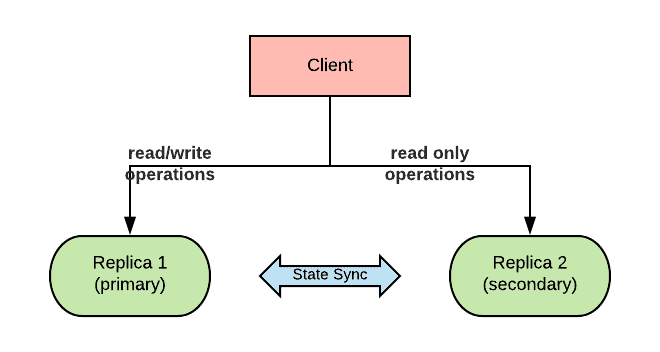
Replicas
Replicas are a way to increase availability of a stateful workload. By having multiple replicas, the workload can continue servicing requests even when one of the replicas becomes unavailable. To do so, replicas’ state must be kept in sync. Replicas can work in master/slave or multimaster mode depending on the implementation. Master replicas can execute both read and write type of requests, while normally slave replicas can only carry out read requests. In addition, replicas can also help with scaling horizontally the workload.
Replicas are called in different ways by different kinds of stateful workloads, but the concept remains roughly the same. The following are some such examples from popular products:
| Product Name | Name used for Replicas |
| ElasticSearch | replica |
| Cassandra | keyspace |
| MongoDB | replica set |
| CockroachDB | replica |
Shards
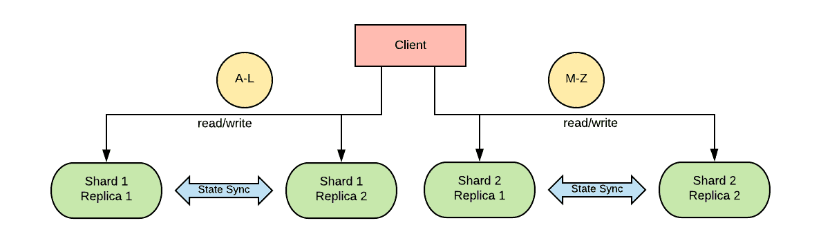
Shards are a way to increase the general throughput of the workload. Usually, the state space is broken down into two or more shards based on a hashing algorithm. The client or a proxy decides where to send requests based on the computed hash. This dramatically increases horizontal scalability, whereas historically for RDBMS, vertical scaling was often the only practical approach.
From an availability perspective, shards do not have a significant impact, although they can decrease the MTTF of the system as a whole. Each shard is an island, and the same availability considerations that apply to a non-sharded database also apply to each individual shard. Stateful workloads can have replicas of shards which sync their state to increase the availability of each individual shard.
Shards, however, while allowing for horizontal scalability, introduce the additional complication of needing to maintain consistency between them. If a transaction involves multiple shards, there needs to be a method to ensure that all of the involved shards are coordinated into participating in their portion of the transaction.
Shards also introduce the issue of deciding how to divide the data. If one has a single data-space that needs sharding, the decision is relatively simple. However, when there are multiple data-spaces in a single database that need sharding, it can be difficult to calculate the optimal sharding policy. Unbalanced or unoptimized shards can impact the availability and performance of the system.
Shards are widely adopted in modern databases to allow for unbounded scalability and need to be taken into consideration especially with regard to the multi-shard consistency issue.
Shards are called in different ways by different kinds of stateful workloads, but the concept remains roughly the same. Examples include:
| Product Name | Name used for Shards |
| ElasticSearch | index |
| Cassandra | partition |
| MongoDB | shards |
| CockroachDB | range |
Putting it all together
The following diagram summarizes many of the concepts that have been discussed thus far and consists of a deployment of a stateful workload with two shards. Each shard has 3 replicas with independent storage volumes.
Consensus Protocols
Consensus Protocols allow for the coordination of distributed processes by agreeing on the actions that will be taken.
Two major families of consensus protocols can be identified: Shared state (between instances) and unshared state.
Shared state better suits the replicas coordination use case while unshared state is preferred by the shard coordination use case.
In shared state consensus protocol, only the strict majority of the instances need to agree on the proposed action, while in unshared state consensus protocol all of the instances need to agree or else the transaction fails.
Consensus protocols should be treated in a similar manner as encryption algorithms; only those that have been thoroughly tested and validated should be trusted.
Shared State Consensus Protocols
A component of shared state consensus protocols is a leader election process. After an agreement from a strict majority of the members of a stateful workload cluster, a leader is designated as the ultimate and undiscussed owner of the state.
As long as the strict majority of the elements of the cluster can communicate with each other, the cluster can continue to operate in a non-degraded state (without violating the CAP theorem). This results in a stateful system that is both consistent and available, while sustaining a number of failures.
In a cluster of two, if a member is lost, the remaining member does not represent the strict majority. In a cluster of three, if a member is lost, the two remaining members do represent the strict majority. As a consequence, for a stateful workload that implements a leader election protocol, there must be at least three nodes to preserve availability and consistency in the presence of one failure (HA-1).
As of today, there are two main generally accepted and formally proven consensus algorithms based on leader election:
- Paxos – Generally considered very efficient, but can be difficult to understand and is challenged by several real world corner cases.
- Raft – Generally considered easy to understand for most real life scenarios, even though it is less efficient.
Most of the new stateful software tends to be based on Raft as it is simpler to implement.
Reliable Replicated State Machines
A replicated state machine (RSM) is a system that executes the same set of operations, in the same order, on several processes. A reliable replicated state machine relies on a consensus protocol to ensure that a set of operations are agreed upon and executed in absolute order by all the instances of a stateful workload.
Notice that given the concept of log of operations in the Raft consensus protocol, with Raft it is easier to implement a Reliable Replicated State Machine.
Reliable Replicated Data Store
Reliable Replicated Data Store builds on the concept of reliably replicated state machines. The goal of the replicated state machine is to store data in datastores.
Reliably replicated data stores are a foundational building block of modern stateful workloads and govern how replicas are synchronized.
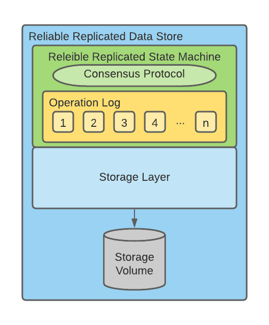
The previous diagram depicts how a Reliable Replicated Data store can be created by combining a reliable Replicated State Machine and a Storage Layer.
Unshared State Consensus Protocols
Unshared state consensus protocols can be used to coordinate processes by agreeing on some action to perform. Notice that the action can be different for each of the processes involved. For this reason a coordinator is needed to orchestrate the involved processes and keep track of what action each process needs to perform. Unshared state consensus protocols are apt at coordinating cross-shard requests.
2PC
2PC (two-phase commit) is a specialized form of consensus protocol used for coordination between participants in a distributed atomic transaction to decide on whether to commit or abort (roll back) the transaction. 2PC is not resilient to all possible failures, and in some cases, outside (e.g. human) intervention is needed to remedy failures. Also, it is a blocking protocol. All participants block between sending in their vote (see below), and receiving the outcome of the transaction from the co-ordinator. If the co-ordinator fails permanently, participants may block indefinitely, without outside intervention. In normal, non-failure cases, the protocol consists of two phases, whence it derives its name:
- The commit-request phase (or voting phase), in which a coordinator requests all participants to take the necessary steps for either committing or aborting the transaction and to vote, either “Yes” (on success) , or “No” (on failure)
- The commit phase, in which case the coordinator decides whether to commit (if all participants have voted “Yes”) or abort, and notifies all participants accordingly.
3PC
3PC adds an additional phase to the 2PC protocol to address the indefinite blocking issue mentioned above. But 3PC still cannot recover from network segmentation, and due to the additional phase, requires more network round-trips, resulting in higher transaction latency
Examples of consensus protocol used by stateful workloads
The following table illustrates several stateful workloads products and their choices in terms of consensus protocols.
| Product | Replica consensus protocol | Shard consensus protocol |
| Etcd | Raft | N/A (no support for shards) |
| Consul | Raft | N/A (no support for shards) |
| Zookeeper | Atomic Broadcast (a derivative of Paxos) | N/A (no support for shards) |
| ElasticSearch | Paxos | N/A (No support for transactions) |
| Cassandra | Paxos | Supported, but details are not available. |
| MongoDB | Paxos | Homegrown protocol. |
| CockroachDB | Raft | 2PC |
| YugabyteDB | Raft | 2PC |
| TiKV | Raft | Percolator |
| Spanner | Raft | 2PC+high-precision time service |
| Kafka | A custom derivative of PacificA | Custom Implementation of 2PC |
Cloud Native Disaster Recovery – An Example Reference Design
This section describes two reference implementation approaches to cloud native disaster recovery as defined at the beginning of this document. The first approach features strong consistency, while the second is an eventual consistency approach.
Strong Consistency
A strong consistency cloud native disaster recovery deployment can be built by picking a stateful workload that favors consistency in the CAP theorem.
The high-level architecture is displayed in the following diagram:
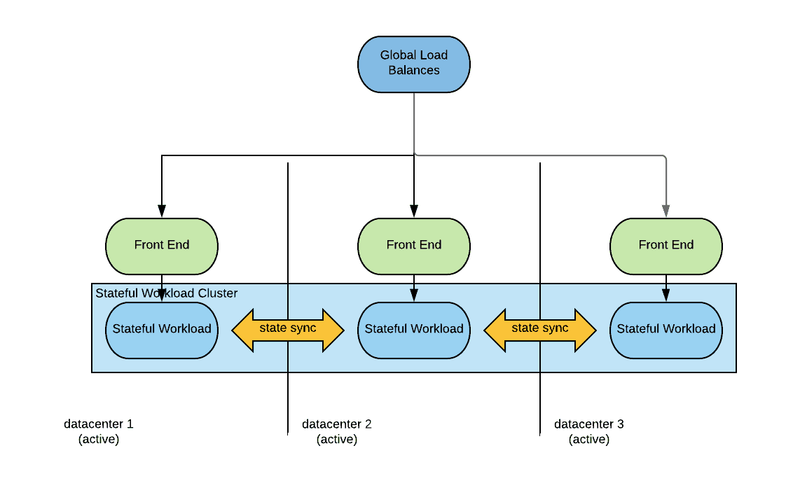
As we can see a global load balancer distributes traffic to the datacenters. The global load balancer should be able to sense the application health in each datacenter with the use of health checks. The global load balancer should also be able to implement different load balancing policies. A common load balancing policy in these scenarios is low latency, where a consumer is redirected to the closest data center, using latency as the metrics for distance.
The traffic may reach directly the stateful workload after being load balanced, but more typically it will reach some stateless front-end tier. The front-end tier will access the stateful workload in the same locality.
The stateful workload can communicate in an east-west fashion with the other instances deployed in the other region/datacenters in order to sync the state.
When a disaster occurs, the global load balancer will detect the unavailability of one of the data centers and redirect all traffic to the remaining active datacenters. No action needs to occur on the stateful workload as it will manage the loss of a cluster member. Likewise when normal operations are resumed the stateful workload will reorganize itself and the recovered instances will become active after catching up with any state loss they may have incurred into. Once the recovered instances become active again the global load balancer will sense that and will resume serving traffic to the recovered data center or regions. No human intervention is needed in either case.
Strongly consistent deployments guarantee an RPO of exactly zero.
Given that in order to guarantee consistency messages have to be replicated across datacenters which have possibly high-latency between them, these architectures may not be suitable for all the applications, especially not for very latency-sensitive applications.
Considerations on network partitioning
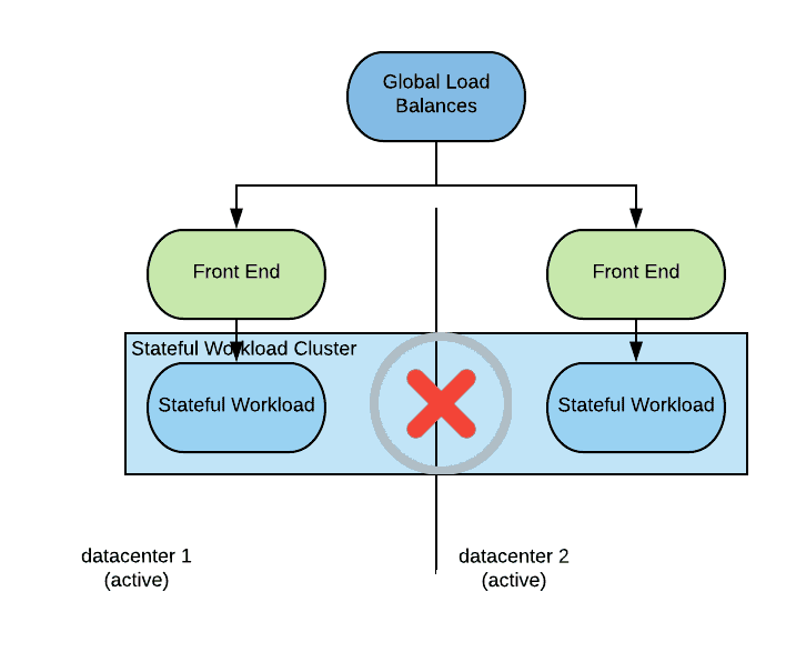
Network partitioning is a situation that requires some attention in this kind of deployments. Network partitioning is different from a disaster situation that takes down an entire datacenter as we have described previously. Here is what a network partition might look like:
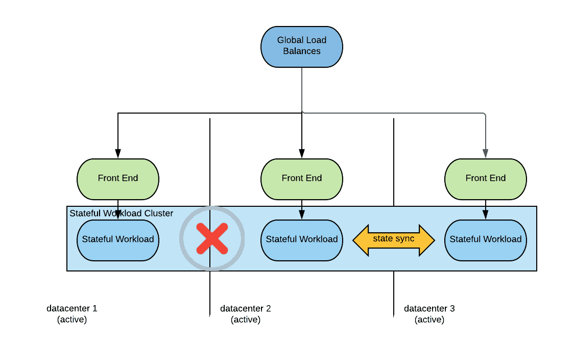
In this situation connectivity between datacenter one and the other datacenters is not possible. Notice that connectivity from outside the data centers may still be possible so from the global load balancer perspective all data centers are still available.
In this situation the because the stateful workload instances in the datacenter 1 cannot reach quorum they will make themselves unavailable. If the global load balancer health check is sophisticated enough to detect that the stateful workload instances are not available, connections will be redirected to the available data centers and the system will behave as when in a disaster situation. If the health checks are not sophisticated enough, consumers connecting to datacenter one will receive an error. In either case consistency of data is guaranteed.
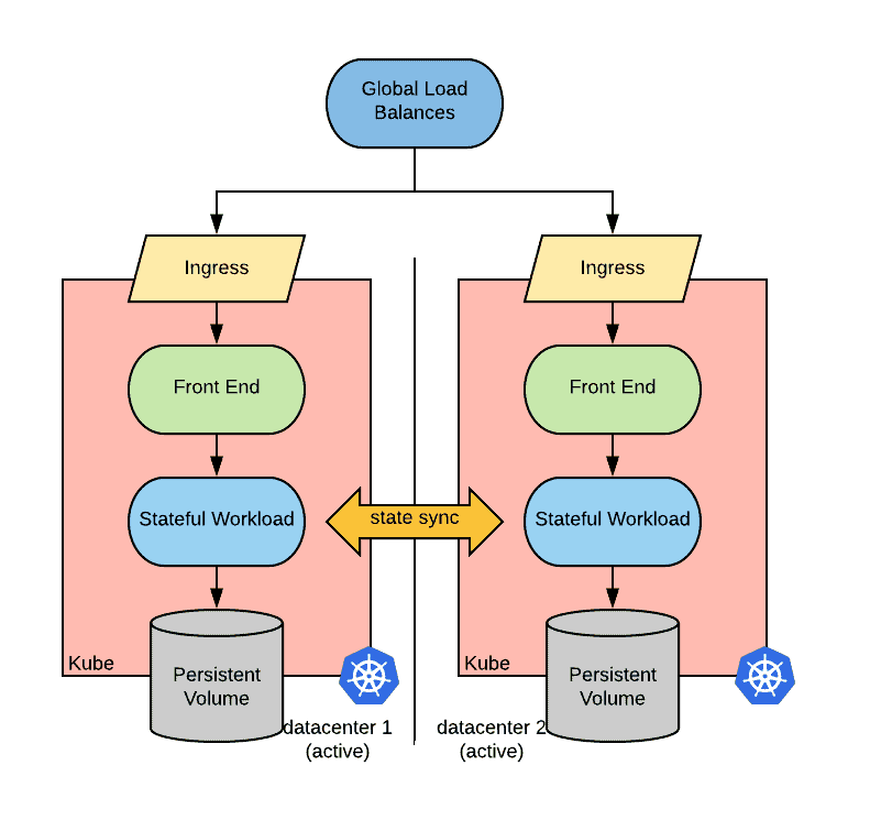
Kubernetes implementation considerations
A possible implementation of the described above active/active strongly consistent strategy in kubernetes is depicted below:
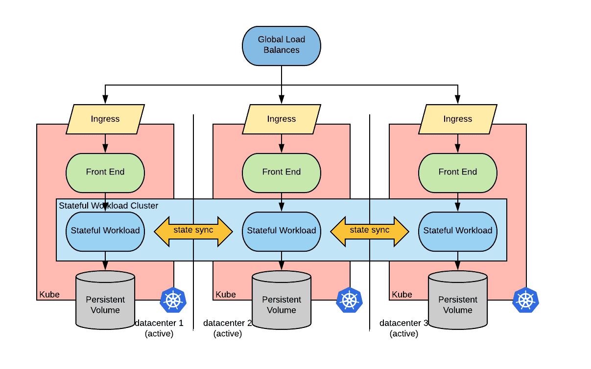
In order to implement this architecture we need the following capabilities:
- A global load balancer with the ability to define health checks. The global load balancer should be configured based on the state of kubernetes clusters. Ideally an operator would do that.
- The ability for the instances of the stateful workload to communicate in an east-west fashion between the clusters. This can be achieved in many ways depending on the CNI implementations. For some CNI implementations, pods are directly routable from outside the pod’s network, in this case cross-cluster discoverability is needed. Other CNI implementations define an overlay network for the pods, in this case an overlay network to overlay network routability is needed. This can be implemented via a network tunnel.
Surprisingly, the capabilities needed for cloud native disaster recovery fall in the networking area rather than in the storage area as one might have expected.rea as one might have expected.
Eventual Consistency
An eventually consistent cloud native disaster recovery deployment can be built by picking a stateful workload that favors availability in the CAP theorem.
The architecture will look as follows:
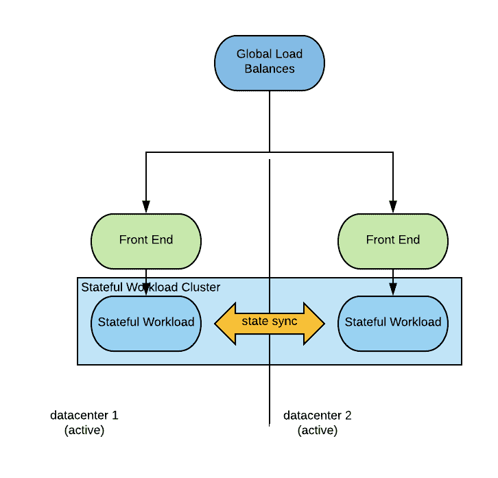
For this discussion, we define as an eventual consistent workload a workload that persists data locally first and then propagates the changes to its peers. This simplification is needed to make the discussion tractable and does not change the conclusions. Many eventually consistent workloads allow you to define the number of copies of the data that have to have been persisted before the transaction can be considered successful. As long as the number of copies is lesser than the strict majority, we still have an eventual consistent behavior, if the number of consistent copies is equal or higher than the strict majority of the instances, then we fall in the strongly consistent camp (see paragraph above).
Differently from a strongly consistent deployment, here we need only two datacenters.
When a disaster occurs, the global load balancer will detect the unavailability of one of the data centers and start direct connections to the other one. This is similar to what happens with strongly consistent deployments, resulting in a RTO close to zero. The main difference from a strongly consistent deployment is that there can be some transactions that have been persisted locally in the datacenter that is hit by the disaster and have not been synched with the other datacenter. The consequence of this is that the RPO of this architecture is not zero. Under normal circumstances the RPO will be very small, likely a multiple of the latency between the two datacenters. But if the system is under stress unsynced transactions will accumulate on one side with no upper bound, yielding a theoretically unbounded RPO (however this is an unlikely situation).
When the disaster situation is recovered, the instances of the stateful workload running in the restored site will sync back automatically and, when ready, the global load balancer will start distributing traffic to both datacenters. No human intervention is required.
Considerations on network partitioning
A network partition scenario for an eventual consistent deployment looks as the following diagram:
As shown in the picture, connectivity between datacenter one and two is interrupted. From a consumer and load balancer perspective though, both data centers are still available. Consumers of this service will be able to connect and operate normally, but the state of the stateful workload will diverge between the two sites.
When the partition condition is removed, the state will converge based on a state reconciliation logic. Notice that this logic does not guarantee that the final state will be correct in the application-specific business logic sense.
Kubernetes implementation considerations
A possible implementation of the described above active/active eventual consistent strategy in kubernetes is depicted below:
The same implementation-related considerations as for the strongly consistent deployment apply here, the main difference is that we need only two data centers/regions.
Examples of Active/Passive Disaster Recovery Strategies
This section describes traditional disaster recovery strategies. These strategies employ active / passive approaches and can be easily implemented with two datacenters. The active / passive nature of these approaches yields worse results than strategies based active / active approaches with regards to the two key metrics of disaster recovery: RTO and RPO. That said, these approaches are still possible in cloud native environments.
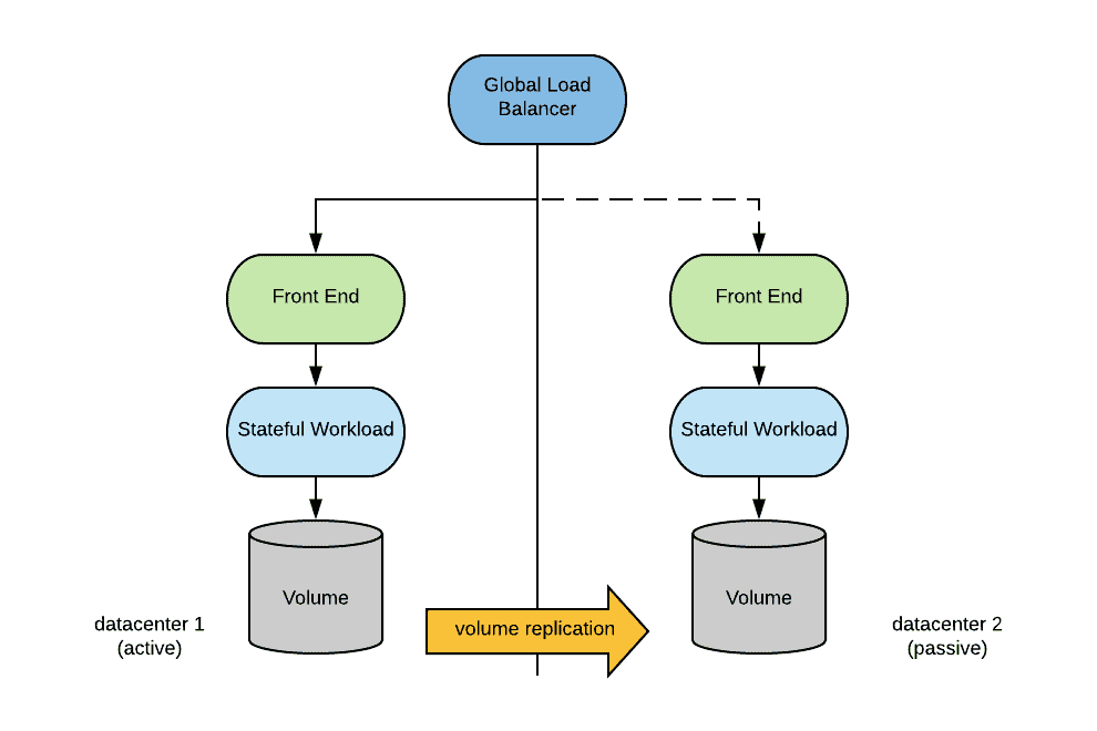
In an active/passive scenario, the overall architecture is depicted below:
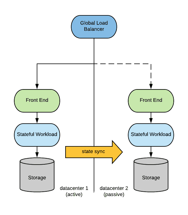
In the preceding diagram, a global load balancer directs traffic to one of the data centers. The application is configured to replicate its state to the passive site.
When a disaster strikes, the following needs to occur:
- The application is activated (either started, or configured to be master) in the passive site.
- The global load balancer needs to be switched to direct traffic to the passive site.
These actions can be automated and performed in a relatively timely fashion. However, the decision to trigger that automation depends on declaring a disaster on the primary site (a task that typically involves human interaction). As a result, downtime is typically experienced by the application.
Once the disaster has been resolved, traffic should be switched back to the primary site. Likely, the easiest way this can be accomplished is to perform the disaster procedure in the opposite direction. Once again, while this procedure can be automated, it will still likely require some downtime.
Previously, we described a very generic process to design an active/passive disaster recovery scenario. The entire architecture hinges on the ability to replicate state from the active site to the passive site. The following are several ways this task can be accomplished. Keep in mind that each workload is different, so these are various approaches that could be used. The ultimate choice depends on the applicability for the target environment.
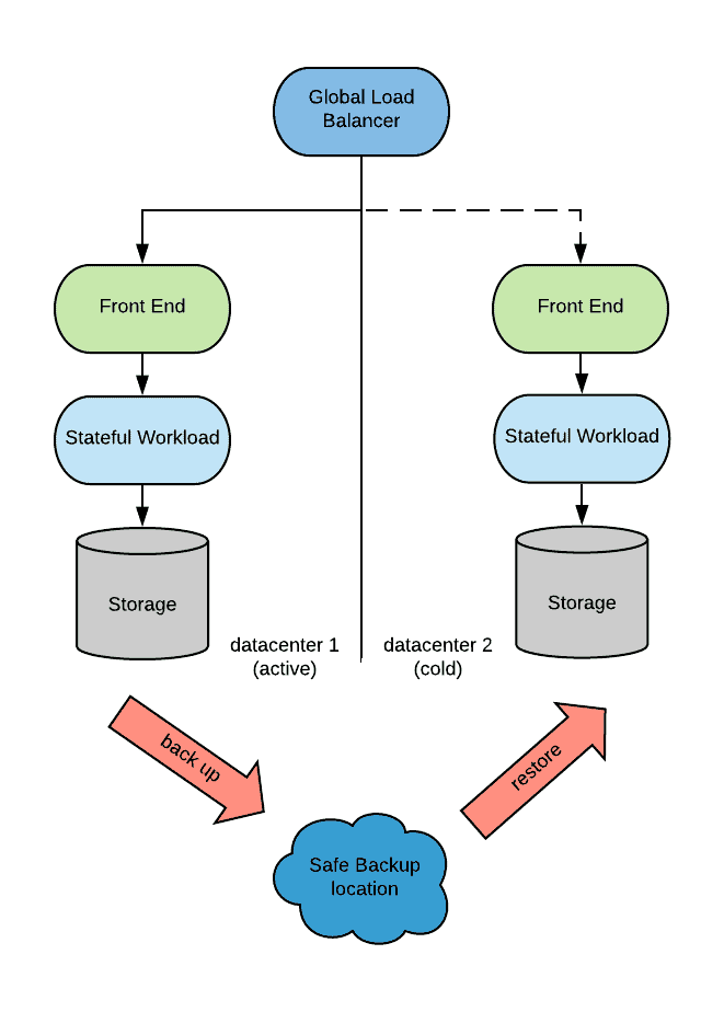
Backups and Restore
While performing backups can provide invaluable protection against application misconfiguration, bugs or human error, there are performance implications that are applied to a DR strategy. In fact, this approach introduces an RPO that is equal to the frequency of backup for the RTO discussed above.
Modern solutions try to backup the stateful workload while it is serving requests. Many databases must be quiesced before taking a snapshot of their storage or else the snapshot risks being inconsistent preventing the database instance on the recovery side from starting. Quiescing, which roughly corresponds to stopping processing requests and flushing all the OS file caches, might be done very quickly, giving the illusion to the user of uninterrupted service.
Considering recreating this deployment with Kubernees, it should be noted that Kubernetes does not natively offer the abstractions of backup and restores (snapshots help close the gap), however there are several storage vendors that have introduced backup and restore options as operators.
Volume-Level Replication
With volume replication, state is replicated at the storage level. Volume replication can be synchronous (typically used on low latency scenarios) or asynchronous. In either case, the application must be designed to operate in a way that guarantees storage is always consistent, or at least recoverable.
Most storage solutions support volume replication, however note that many stateful workloads do not cope well with volume-level replication and there is a risk of data corruption when using this approach.
When implementing this approach in Kubernetes, one should consider that Kubernetes does not offer a standard primitive to set up volume replication between two different clusters. So, at least for the time being, a non native Kubernetes-standard extensions must be used to support this capability.
Configuring volume replication outside of the Kubernetes abstraction is always a possibility. However, since the static nature of this method of configuration usually conflicts with dynamic volume provisioning, careful considerations must be taken into the design.
Application Level Replication
With application level replication, the replication is facilitated by the application itself. Again, the replication can be synchronous or asynchronous. Because the replication is application-driven,, there is a guarantee that storage will always be in a consistent state. Most traditional databases can be configured in this fashion with a primary running in the active site, and a secondary running in the passive site.
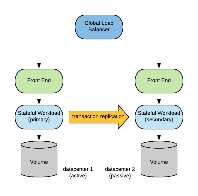
In order for the primary to synchronize with the secondary, it must be possible to establish a connection from the master instance to the slave instance (and vice-versa when recovering after a disaster).
A possible solution to address this issue is to establish a network tunnel between the clusters in such a way that pods in one cluster can directly communicate to pods in the other clusters.
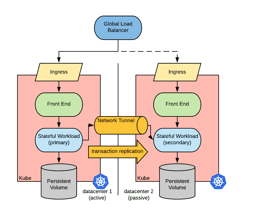
Unfortunately, Kubernetes does not offer a standard abstraction to create network tunnels between clusters. However, there are community projects that offer this functionality including Submariner and Cilium.