
Guest post by Karen Bruner, Technical Evangelist, StackRox. Original article can be found here.
Kubernetes cluster networking can be more than a bit confusing, even for engineers with hands-on experience working with virtual networks and request routing. In this post, we will present an introduction into the complexities of Kubernetes networking by following the journey of an HTTP request to a service running on a basic Kubernetes cluster.
We will use a standard Google Kubernetes Engine (GKE) cluster with two Linux nodes for our examples, with notes on where the details might differ on other platforms.
A request’s journey
Take the typical example of a person browsing the web. They click on a link, something happens, and a page loads.

We need to fill in those question marks a bit.
In the next diagram, the request gets sent through the Internet to a very large cloud provider, then to a Kubernetes cluster hosted in the cloud provider’s infrastructure.

Guide to Kubernetes network policies
As we zoom in closer to the Kubernetes cluster, we see a cloud provider load balancer feeding to a Kubernetes Service resource, which then routes requests to pods in a Kubernetes ReplicaSet.
apiVersion: apps/v1
kind: ReplicaSet
metadata:
  name: hello-world
  labels:
    app: hello-world
spec:
  selector:
    matchLabels:
      app: hello-world
  replicas: 2
  template:
    metadata:
      labels:
        app: hello-world
    spec:
      containers:
      - name: hello-world
        image: gcr.io/google-samples/node-hello:1.0
        imagePullPolicy: Always
        ports:
        - containerPort: 8080
          protocol: TCP

---
apiVersion: v1
kind: Service
metadata:
  name: hello-world
spec:
  selector:
    app: hello-world
  ports:
  - port: 80
    targetPort: 8080
    protocol: TCP
  type: LoadBalancer
  externalTrafficPolicy: Cluster
These manifests should result in the creation of two pods as part of the hello-world ReplicaSet, and a hello-world service resource with an external-facing load balancer, if the cloud provider and cluster network supports it. It should also create a Kubernetes Endpoint resource with two entries in the host:port notation, one for each of the pods, with the pod IP as the host value and port 8080.
On our GKE cluster, querying these resource types with kubectl returns the following:
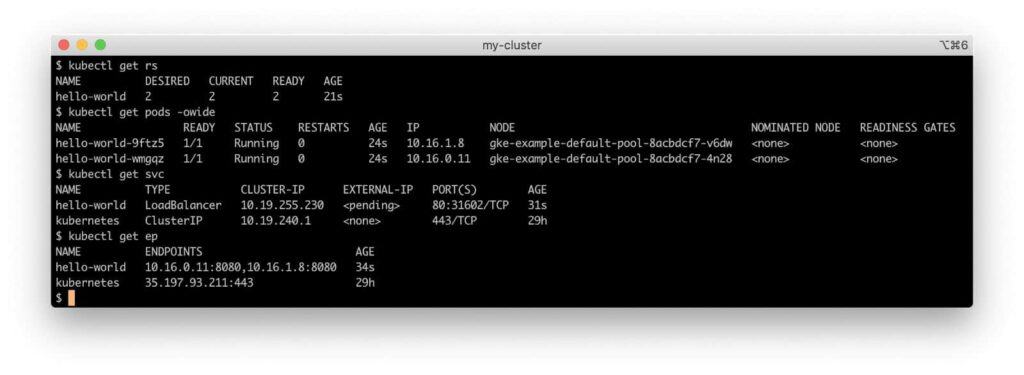
For reference, our cluster has the following IP networks:
- Node – 10.138.15.0/24
- Cluster – 10.16.0.0/14
- Service – 10.19.240.0/20
Our service has a Virtual IP address (VIP) of 10.19.240.1 in the cluster CIDR block.
We are now ready to follow the request’s journey into the Kubernetes cluster, beginning at the load balancer.
The load balancer
While Kubernetes, both natively and through ingress controllers, offers a number of ways to expose a service, we will use the standard Service resource of type LoadBalancer. Our hello-world service needs a GCP network load balancer. Every GKE cluster has a cloud controller, which interfaces between the cluster and the API endpoints for GCP services needed to create cluster resources automatically, including our load balancer. (All cloud providers offer different classes of load balancers with varying options and characteristics.)
To see where the external load balancer fits in, first we need to look at the cluster from a different viewpoint.

kube-proxy
Each node has a kube-proxy container process. (In the Kubernetes frame of reference, that kube-proxy container is in a pod in the kube-system namespace.) kube-proxy manages forwarding of traffic addressed to the virtual IP addresses (VIPs) of the cluster’s Kubernetes Service objects to the appropriate backend pods. kube-proxy currently supports three different operation modes:
- User space: This mode gets its name because the service routing takes place in
kube-proxyin the user process space instead of in the kernel network stack. It is not commonly used as it is slow and outdated. - iptables: This mode uses Linux kernel-level Netfilter rules to configure all routing for Kubernetes Services. This mode is the default for
kube-proxyon most platforms. When load balancing for multiple backend pods, it uses unweighted round-robin scheduling. - IPVS (IP Virtual Server): Built on the Netfilter framework, IPVS implements Layer-4 load balancing in the Linux kernel, supporting multiple load-balancing algorithms, including least connections and shortest expected delay. This
kube-proxymode became generally available in Kubernetes 1.11, but it requires the Linux kernel to have the IPVS modules loaded. It is also not as widely supported by various Kubernetes networking projects as the iptables mode.
kube-proxy in our GKE cluster runs in iptables mode, so we will look at how that mode works.
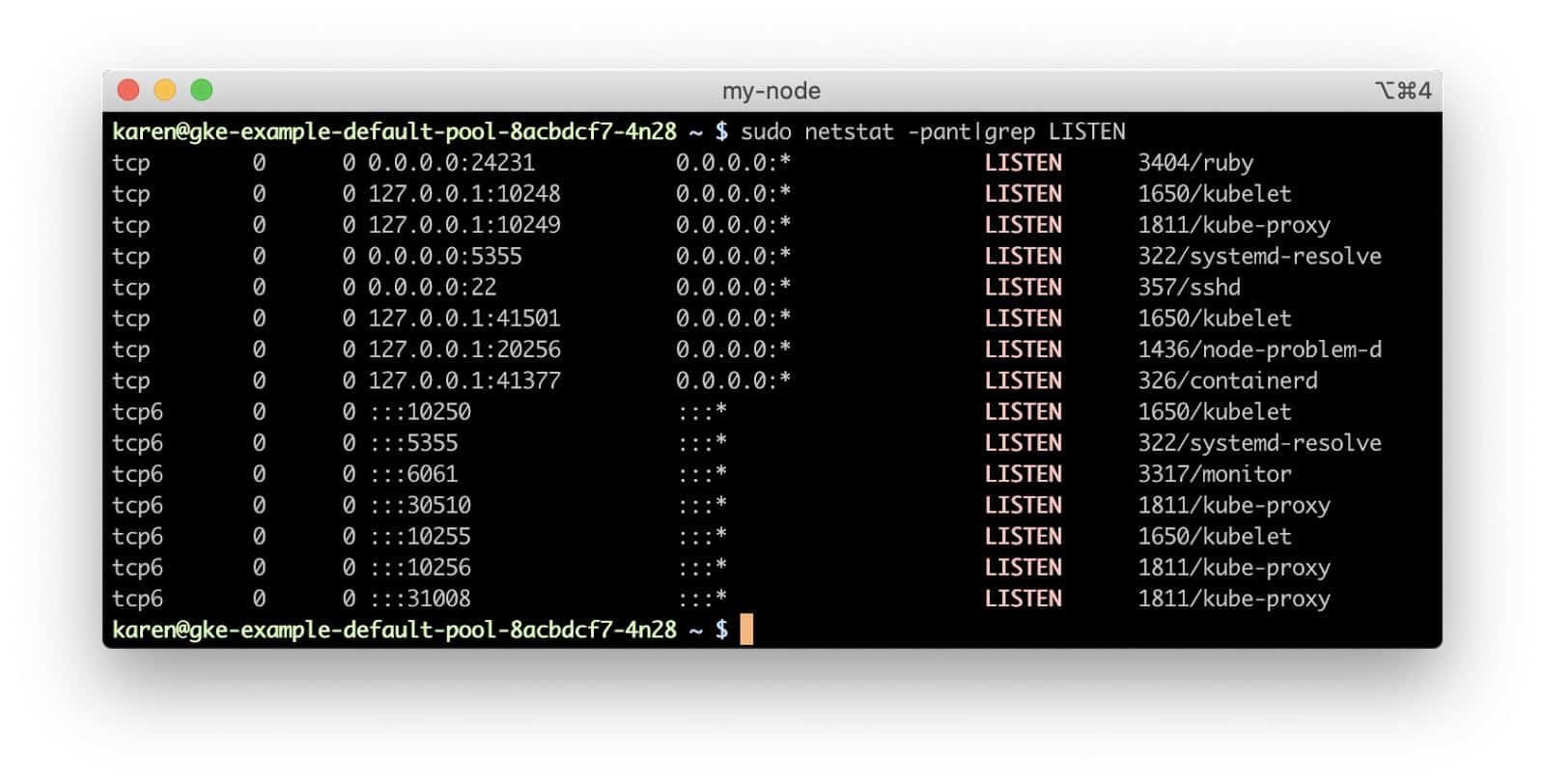
If we look at the hello-world service we created, we can see that it has been assigned a node port (a network port for the node’s IP address) of 30510. Dynamically-assigned ports on the node network allow multiple Kubernetes services hosted in the cluster to use the same Internet-facing port in their endpoints. If our service had been deployed to a standard Amazon Elastic Kubernetes Service (EKS) cluster, it would be served by an Elastic Load Balancer which would send incoming connections to our service’s node port on nodes with a live service pod. However, Google Cloud Platform (GCP) network load balancers only forward traffic to the targets on the same port as the incoming port on the load balancer, i.e., traffic to port 80 on the load balancer will be sent to port 80 on the target backend instance. The hello-world pods are definitely not listening on port 80 of the node. If we run netstat on the node, we see that no process is listening on that port.
So how do requests through the load balancer make a successful connection? If kube-proxy were running in the user space mode, it would actually be proxying connections to backend pods. In iptables mode, though, kube-proxy configures Netfilter chains so the connection is routed directly to the backend container’s endpoint by the node’s kernel.
iptables
In our GKE cluster, if we log in to one of the nodes and run iptables, we can see these rules.
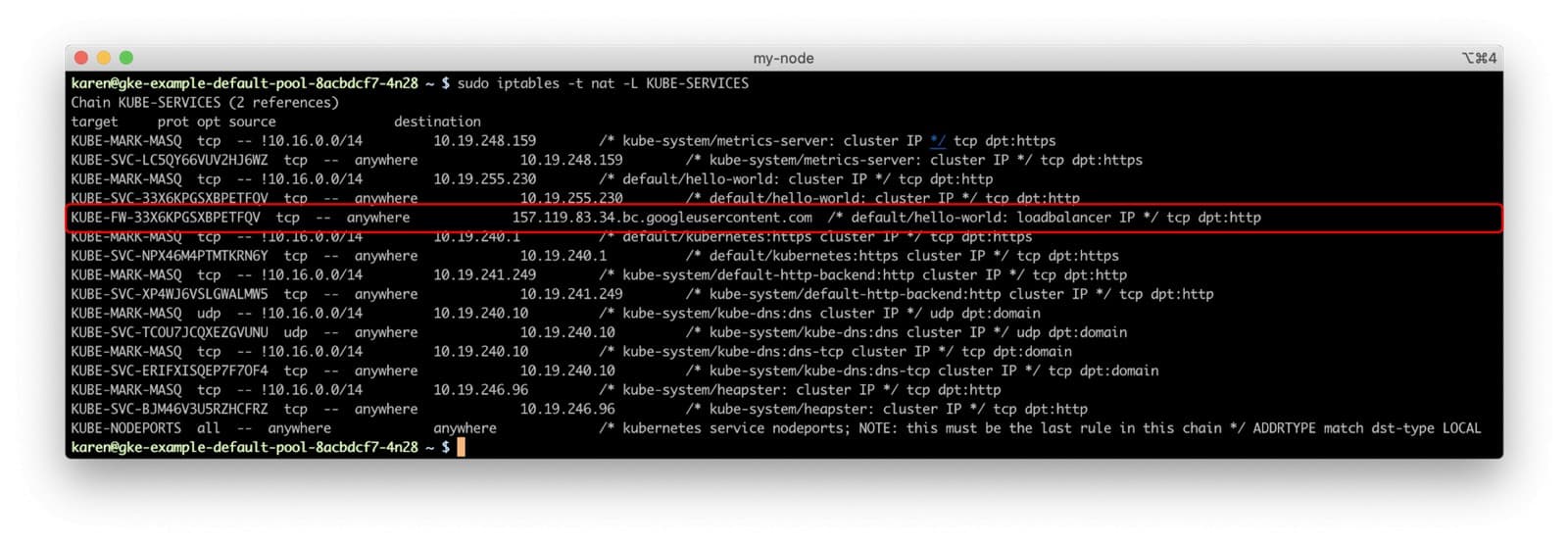
Thanks to the rule comments, we can get the name of the filter chain that matches incoming connections from the service’s load balancer to our hello-world service and follow that chain’s rules. (In the absence of a rule comment, we still could have matched the rule’s source IP address to the service’s load balancer.)
We can also visualize the chains and rules used in the network stack for evaluating and modifying the packet to see how the service we created in our cluster directs traffic to the replica set members.

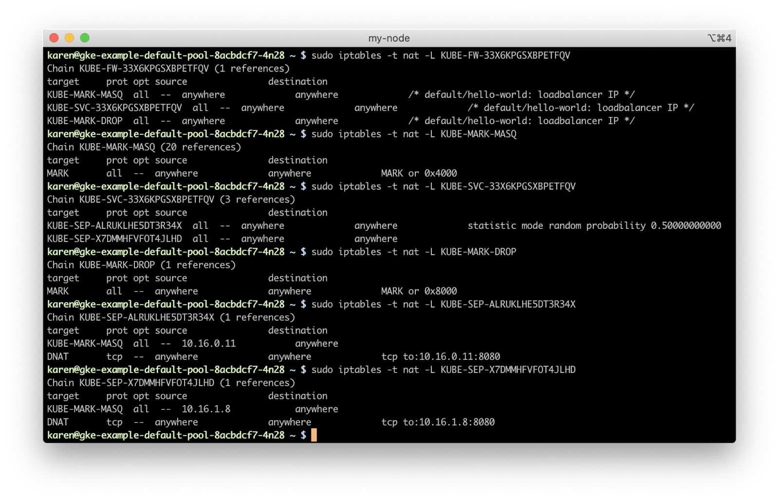
The KUBE-FW-33X6KPGSXBPETFQV chain has three rules, each adding another chain for handling the packet.
KUBE-MARK-MASQadds a Netfilter mark to packets destined for thehello-worldservice which originate outside the cluster’s network. Packets with this mark will be altered in aPOSTROUTINGrule to use source network address translation (SNAT) with the node’s IP address as their source IP address.- The
KUBE-SVC-33X6KPGSXBPETFQVchain applies to all traffic bound for our hello-world service, regardless of source, and has rules for each of the service endpoints (the two pods, in this case). Which endpoint chain to use gets determined in a purely random fashion.KUBE-SEP-ALRUKLHE5DT3R34XKUBE-MARK-MASQagain adds a Netfilter mark to the packet for SNAT, if needed- The
DNATrule sets up a destination NAT using the 10.16.0.11:8080 endpoint as the destination.
KUBE-SEP-X7DMMHFVFOT4JLHDKUBE-MARK-MASQagain adds a Netfilter mark to the packet for SNAT, if needed- The
DNATrule sets up a destination NAT using the 10.16.1.8:8080 endpoint as the destination.
KUBE-MARK-DROPadds a Netfilter mark to packets which do not have destination NAT enabled by this point. These packets will be discarded in theKUBE-FIREWALLchain.
Note that, even though our cluster has two nodes, each with a hello-world pod, this routing method shows no preference for routing to the pod on the node that receives the request from the cloud load balancer. If we change the externalTrafficPolicy in the service spec to Local, however, that would change. Not only would the request go to a pod on the node receiving the request, if one exists, but it also means a node without a service pod will refuse the connection. Therefore the Local policy generally needs to be used with Kubernetes daemon sets, which schedule a pod on each node in the cluster. While specifying local delivery would obviously reduce the mean network latency for requests, it can lead to uneven load across the service’s pods.
The Pod Network
This post will not dive into details on pod networking, but in our GKE cluster, the pod network has its own CIDR block separate from the node’s network. The Kubernetes network model requires all pods in the cluster to be able to address each other directly, regardless of their host node. GKE clusters use the kubenet CNI, which creates network bridge interfaces to the pod network on each node, giving each node its own dedicated CIDR block of pod IP addresses to simplify allocation and routing. The Google Compute Engine (GCE) network can route this pod network traffic between VMs.
The Request
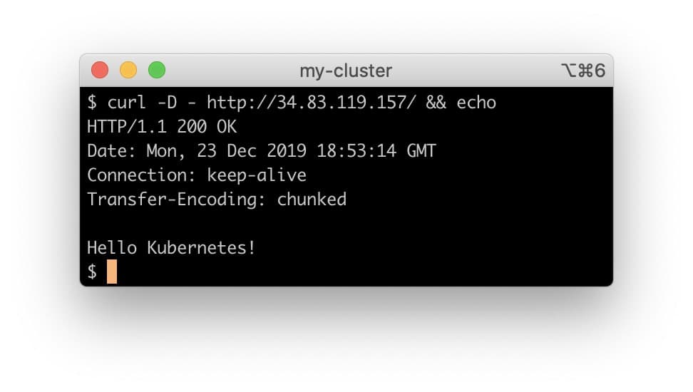
And this is how we get our HTTP 200 response code.
Routing Variables
This post mentioned some of the ways different options offered by various Kubernetes platforms can change routing. Here is a non-comprehensive list:
- Container Network Interface (CNI) plugins: Each cloud provider defaults to a CNI implementation compatible with their VM network model. This post used a GKE cluster with default settings as an example. Examples in Amazon EKS would have looked very different, because the AWS VPC CNI places pods directly on the nodes’ VPC network.
- Kubernetes Network Policy: One of the most popular CNI plugins implementing network policies, Calico, creates a virtual network interface on the nodes for each pod and uses Netfilter rules to enforce its firewall rules.
- The
kube-proxyIPVS routing mode moves the service routing and NATing out of the Netfilter rules, for the most part, although it does still make use of Netfilter. - External load balancers or other sources which can send traffic directly to the service’s node port would match a different chain (
KUBE-NODEPORTS) in iptables. - Kubernetes ingress controllers may change edge service routing in a number of ways.
- Service meshes like Istio may bypass
kube-proxyand make direct connections for internal routing between service pods.
Securing Services
- No universal method for adding firewall restrictions to cloud load balancers that are created by Kubernetes Service resources exists. Some cloud providers honor the
loadBalancerSourceRangesfield in the Service spec, which allows you to provide a whitelist of IP CIDR blocks allowed to connect to the load balancer. If a cloud provider does not honor this field, it will be silently ignored, so take care to verify the network configuration of your external load balancers. For providers that do not support theloadBalancerSourceRangesfield, you should assume your service endpoints on the load balancers will be open to the world unless you take action at the cloud provider level to lock down the load balancers and the cloud networks on which they run. The default firewall settings for cloud provider load balancer offerings vary wildly and depend on many factors. Some cloud providers may also support annotations to theServiceobject to configure load balancer security. - Note that we did not install the Calico CNI by enabling Kubernetes Network Policy support in our GKE cluster, because Calico creates a large number of additional iptables rules, adding extra steps when visually tracing virtual routing to a pod. However, we strongly recommend using a CNI that implements the
NetworkPolicyAPI in production clusters and creating policies that restrict pod traffic. - Pods created with the
HostNetworkattribute enabled will share the node’s network space. While some valid use cases exist for doing so, generally most pods do not need to be on the host network, and particularly for pods running with root privileges, it could allow a compromised container to sniff network traffic. If you need to expose a container port on the node’s network and using a Kubernetes Service node port does not meet your needs, you have the option of specifying ahostPortfor the container in the PodSpec. - Pods using the host network should not run with the
NET_ADMINcapability, which would allow them to read and modify the node’s firewall rules.
The Kubernetes network requires a large number of moving pieces. It is quite complicated, but having a basic understanding of what is taking place in your cluster will help you more effectively monitor, secure, and protect it.
Sources and Further Reading
- https://kubernetes.io/docs/concepts/services-networking/service/
- https://kubernetes.io/docs/concepts/cluster-administration/networking/
- https://twitter.com/thockin/status/1191766983735296000
- https://kubernetes.io/blog/2018/07/09/ipvs-based-in-cluster-load-balancing-deep-dive/
- https://netfilter.org/documentation/HOWTO/NAT-HOWTO-6.html